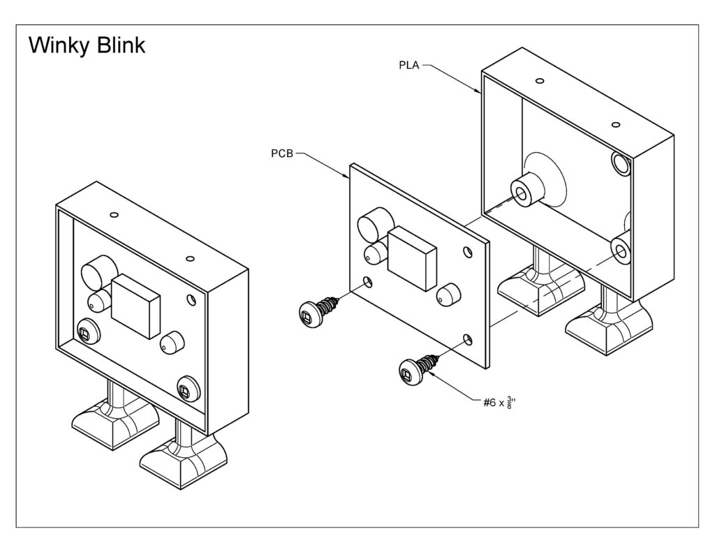
Winky Blink
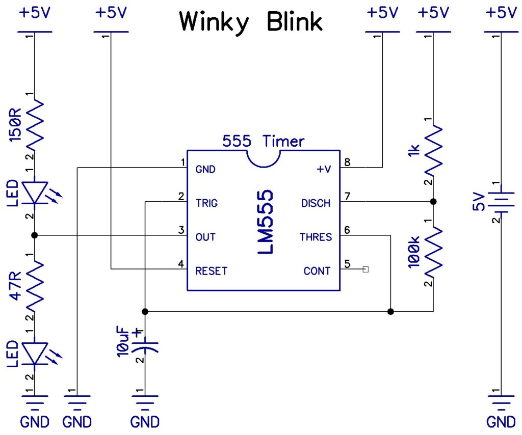
Schematic
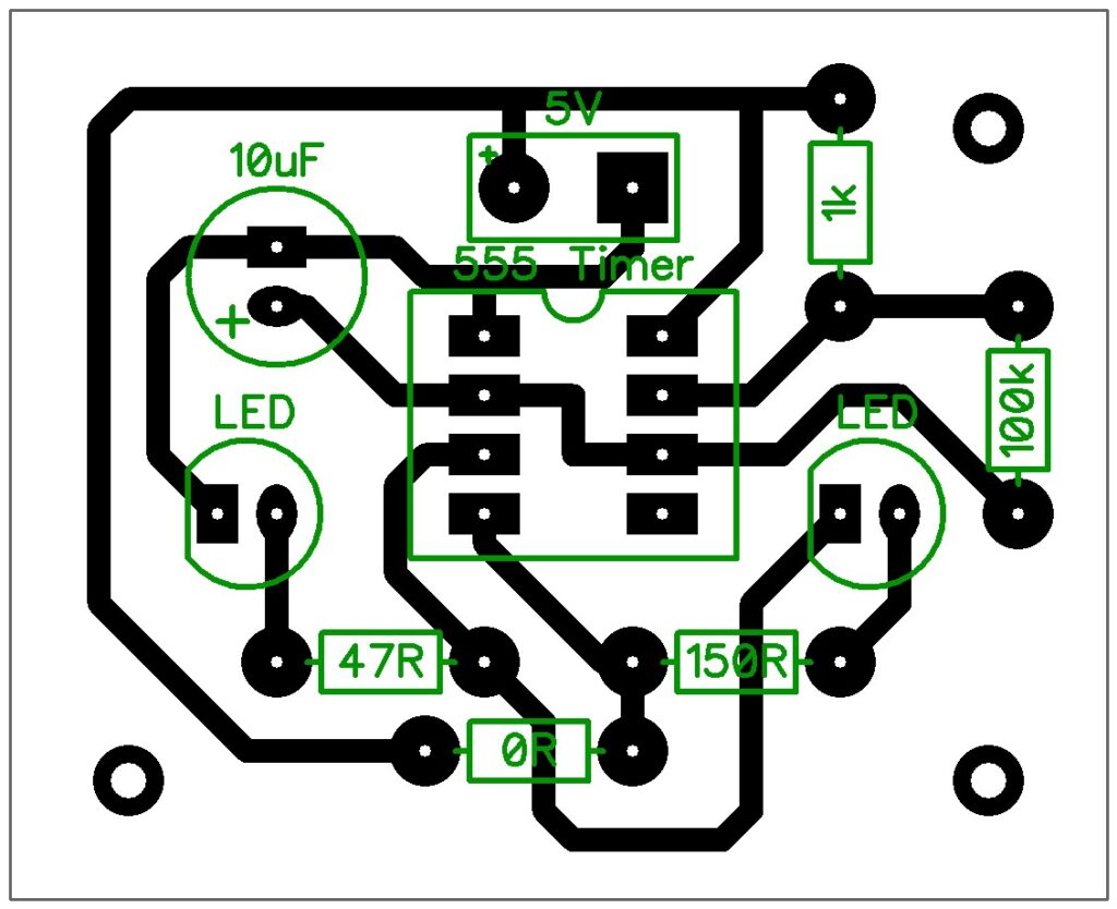
PCB
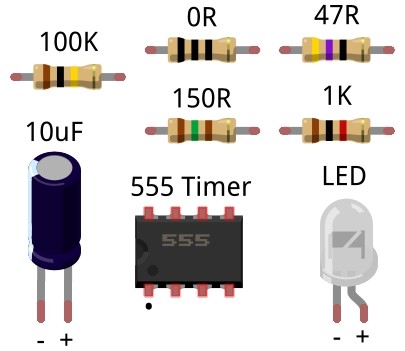
Components
The 555 timer has a either a mark at the top (left side in the diagram) or a dot to mark pin 1. Double check the PCB diagram before soldering it in place.
The jumper (0R resistor) is often marked with a single black line instead of the three black lines used in the diagram.