Assignment #5 Spur Gears
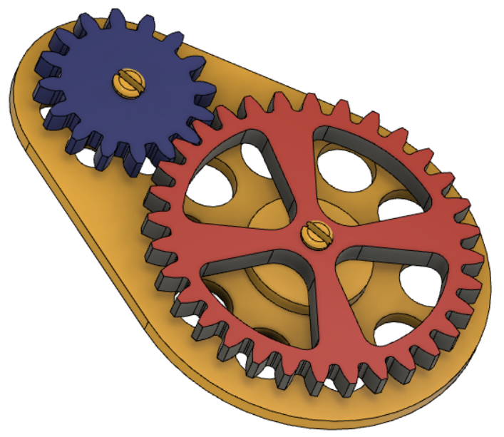
In this exercise you will model and 3D Print a set of ‘spur’ gears. After which you will create a drawing for each component of the assembly.
Modelling
- Tutorial 1 – spur gears, add-ins and creating your first gear
- Tutorial 2 – second gear creation and positioning
- Tutorial 3 – making a base plate
- Tutorial 4 – making the gears turn
- Tutorial 5 – removing unnecessary material
3D Printing
To 3D print a model made in Fusion 360 on our classroom printers, the model will need to be saved in an ‘.stl’ file format and then imported to ‘slicer’ software, Tinkerine Suite 2.0 to prepare it for the printer.
- Tutorial 6 – Creating 3D printable ‘.stl’ files in Fusion 360
- Tutorial 7 – How to 3D Print Using Tinkerine Suite 2.0
Making Drawings (needed for Laser and CNC router)
To make your gears using the CNC Laser/Router you will need to create three pdf drawings, one for each part.
Laser Cutting
- Tutorial 8 – Using Inkscape to set line types for the Laser
- Tutorial 9 – Moving from Inkscape to the Laser’s Universal Control Panel (UCP)
- LASER OPERATION GUIDE_Gears
CNC Routing
- Tutorial 11 – Importing pdf files to VCarve and setting up a ‘job’
- Tutorial 12 – Creating ‘tool paths’ in VCarve & saving to USB for routing
- Tutorial 13 – Using the CNC router (pdf)
Reference Only
The following are orthographic style engineering drawings of the parts. These are far more detailed than what is needed for our purposes. They have been included simply for reference only.
Sample drawings for reference: Spur Gear Project Drawings (base plate & 32T gear)
